Introducing EzONE 1.2
EzONE 1.2, the latest edition of E-ONE’s web-based truck configuration system, is now available to all dealers.
EzONE 1.2 offers better performance and more information about option compatibility and rules. Overall, a 56% performance improvement was reached. Processing times were reduced by streamlining the way EzONE handles rules and communicates information to the user.
Processing time has also been improved for specific selections including:
Cord Reels, Hydraulic Reels, Air Reels
Additional Compartment Lights
Note: All elements of the Configurator, including pages, buttons, tabs, and sections within each module will change periodically with each new release and may differ than what the screen shots in this topic show. Please be patient with this Configurator as it takes a huge amount of memory and CPU resources even on a fast computer with the latest technologies.
To create a new configuration from a new quote, follow these steps:
Connect to the Internet.
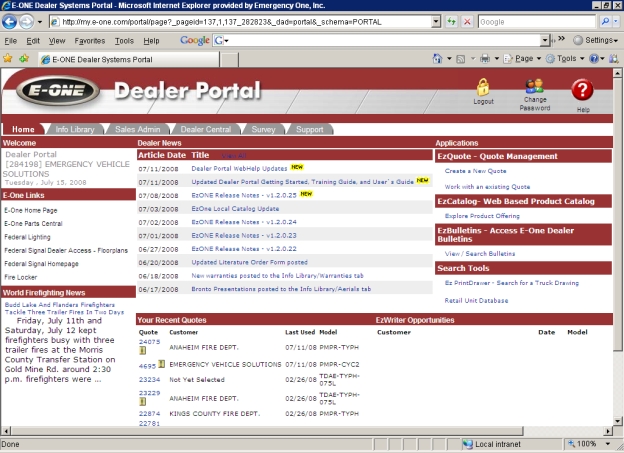
Log into the Dealer Portal .
From the Applications and EzQuote - Quote Management sections of the Dealer Portal, click the Create a New Quote link.
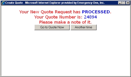
The Create Quote window appears. Click the Go to Quote Now button When this button is clicked the EzQuote window appears and you are on the Quote tab.Quote tab Displays the Quote Number:, Unit Information:, Customer Information:, Dealer Reference:, Date Information: and Quote Actions: sections on the quote window..Quote tab .Quote tab .Quote tab .Quote tab .Quote tab .Quote tab .Quote tab .Quote tab .Quote tab .Quote tab .Quote tab .Quote tab .Quote tab .Quote tab .Quote tab .Quote tab .EzQuote window Displays the Quote Number:, Unit Information:, Customer Information:, Dealer Reference:, Date Information: and Quote Actions: sections. appears and you are on the Quote tab .EzQuote window appears and you are on the Quote tab .EzQuote window appears and you are on the Quote tab .EzQuote window appears and you are on the Quote tab .EzQuote window appears and you are on the Quote tab .EzQuote window appears and you are on the Quote tab .EzQuote window appears and you are on the Quote tab .EzQuote window appears and you are on the Quote tab .EzQuote window appears and you are on the Quote tab .EzQuote window appears and you are on the Quote tab .EzQuote window appears and you are on the Quote tab .EzQuote window appears and you are on the Quote tab .EzQuote window appears and you are on the Quote tab .EzQuote window appears and you are on the Quote tab .EzQuote window appears and you are on the Quote tab .EzQuote window appears and you are on the Quote tab .EzQuote window appears and you are on the Quote tab .EzQuote window appears and you are on the Quote tab .EzQuote window appears and you are on the Quote tab .EzQuote window appears and you are on the Quote tab .EzQuote window appears and you are on the Quote tab .EzQuote window appears and you are on the Quote tab .EzQuote window appears and you are on the Quote tab .EzQuote window appears and you are on the Quote tab .EzQuote window appears and you are on the Quote tab .EzQuote window appears and you are on the Quote tab .EzQuote window appears and you are on the Quote tab .EzQuote window appears and you are on the Quote tab .EzQuote window appears and you are on the Quote tab .EzQuote window appears and you are on the Quote tab .EzQuote window appears and you are on the Quote tab .EzQuote window appears and you are on the Quote tab .EzQuote window appears and you are on the Quote tab .EzQuote window appears and you are on the Quote tab .EzQuote window appears and you are on the Quote tab .EzQuote window appears and you are on the Quote tab .EzQuote window appears and you are on the Quote tab .EzQuote window appears and you are on the Quote tab .EzQuote window appears and you are on the Quote tab .EzQuote window appears and you are on the Quote tab .EzQuote window appears and you are on the Quote tab .EzQuote window appears and you are on the Quote tab .EzQuote window appears and you are on the Quote tab .EzQuote window appears and you are on the Quote tab .EzQuote window appears and you are on the Quote tab .EzQuote window appears and you are on the Quote tab .EzQuote window appears and you are on the Quote tab .EzQuote window appears and you are on the Quote tab .EzQuote window appears and you are on the Quote tab ..
Note: If you click the Another time button, the quote number won't appear in the Your Recent Quotes section until the Dealer Portal page is refreshed or you hit the F5 key to refresh it.
The EzQuote window appears and you are on the Quote tab.

Click on the red icon with the wrench to enter the Configurator.

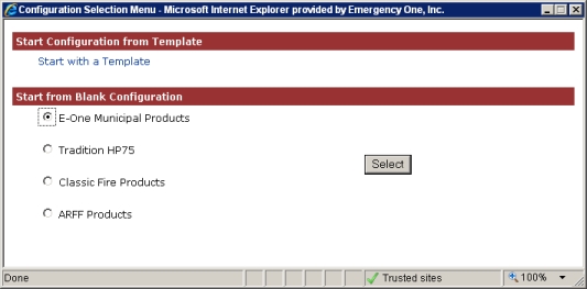
The Configuration Selection Menu window appears. In this example, select E-One Municipal Products from the Start from Blank Configuration section and click the Select button.
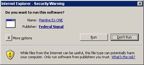
The first time you enter the Configurator on a new quote or on existing quote, you may see a yellow bar in the Configurator window prompting you to 'Click Here to Install the ActiveX Control'. Go ahead and do so. Next, click Install ActiveX control.
You will also see this Internet Explorer - Security Warning dialog box. Click the Run button to run the software. A progress bar will appear. Please wait for the Mainline.XRA module to download and install on your computer.
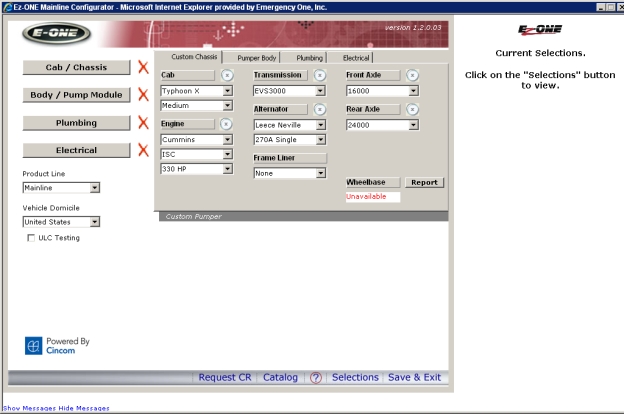
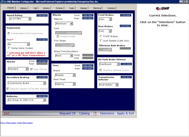
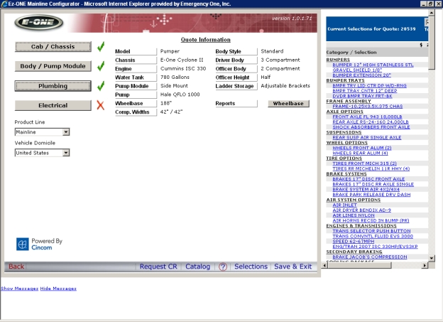
The Ez-ONE Mainline Configurator window and the model page is displayed with these available models:
Pumper / Rescue Pumper
Aerial
Rescue
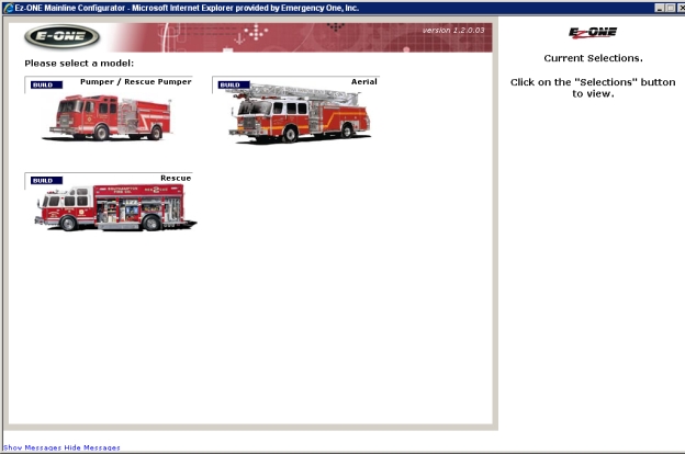
In this example, the Build button is clicked for Pumper / Rescue Pumper.
The Ez-ONE Mainline Configurator window and the second model page is displayed with these available models:
E-ONE Pumper CAT/CST
E-ONE Rescue Pumper CAR/CSR
E-ONE Synergy
Commercial Pumper CAT/CST
Commercial Rescue Pumper CAR/CSR
Commercial Synergy
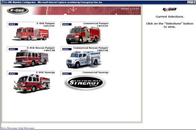
In this example, the Build button is clicked for E-ONE Pumper CAT/CST.
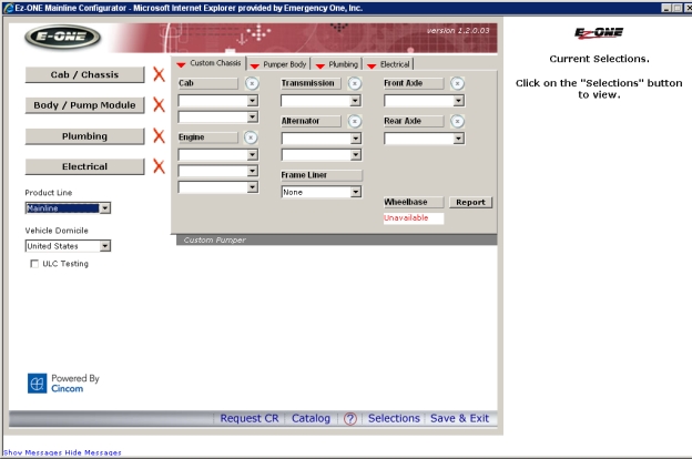
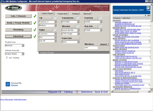
Replacing the Unit Information area in the middle
of the Hub is a group of tabs representing each product group. The selections
on these tabs have been moved from the corresponding modules. These selections
must be completed before visiting the corresponding module. For example,
the selections on the Custom Chassis tab Clicking this tab will display these links: Cummins ISC Spec Sheet,
Cummins ISL Spec Sheet, Cummins ISM Spec Sheet, Cyclone 2 - 07 Cooled
EGR ISM450, Cyclone 2 - 07 Cooled EGR ISM500 Trans Eng, Cyclone 2 - 07
ISL425 Certification, DDEC Engine Coolant Selections, DDEC Engines Lube
Oil Fuel Requirements, DDEC Series 60 Limited Warranty, DDEC Series 60
Spec Sheet, MBE 900 Engine Brouchure, MBE 900 Limited Warranty, and Typhoon
07 ISL425 Certification.
must be completed before clicking on the Cab/Chassis
button Clicking this button in the Mainline Configurator Creates a new configuration from a new quote. will load the Cab/Chassis .XRA module and allow you to configure items for that module.Configurator will load the Cab/Chassis .XRA module and allow you to configure items for that module.Configurator will load the Cab/Chassis .XRA module and allow you to configure items for that module.Configurator will load the Cab/Chassis
.XRA module and allow you to configure items for that module.
to visit that module. The red arrows on the tabs are required selections
that must be made. Clicking the
silver  allows you to clear out the selections made.
As selections are made on the Hub menu tabs, messages may appear in the lower area of the Hub menu advising about changes that may need to be made.
Changing some driving selections may require a visit to one or more of the modules. For example, changing the Cab Model selection would require a visit to the Cab/Chassis module.
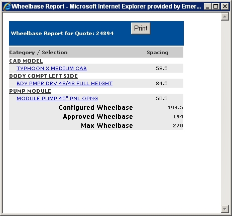
Note: Wheelbase calculations are available for Commercial Pumpers / Rescue Pumpers after the Cab / Chassis module is configured.
Clicking the Report button will display the current wheelbase calculations in a Wheelbase Report window.
The Product Line allows selection of either Mainline or American Eagle A Product Line selection on the EzONE Hub menu will allow the conversion of a quote from Mainline to American Eagle and back again, at any time. or Tradition. In this example, Mainline is selected.
The Vehicle Domicile allows selection of United States, Canada, or Other for English or Metric gauges from the drop down list.
Note: Part number 1400-0011, Battery Splash Cover for ULC compliance will be added to the quote when Canada is selected and the ULC Testing check box is checked.
At the bottom of the Mainline Configurator window these buttons are available:
Request CR: Clicking this button will display the Customer Salescode Request window .
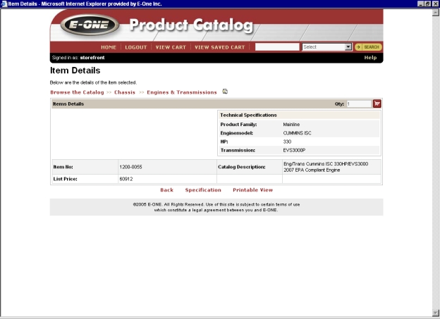
Catalog button: Clicking this button will display the Product Catalog The Product Catalog is a database of options, grouped into detailed categories that can be searched and browsed utilizing a search engine by selecting a make and model of apparatus and "drilling down" into each category level. Items can be retrieved by selecting values for each item and search result. Finally, the attributes and properties of each item can be compared side-by-side such as sales codes, catalog descriptions, manufacturers, and list pricing. .
Question mark or Help icon Click this Question mark icon to get help from the Dealer Portal A Web based server application that runs in Microsoft® Internet Explorer® utilizing Web services on the Internet. This application improves and simplifies your sales process. WebHelp. A help window will appear.Dealer Portal WebHelp. A help window will appear.Dealer Portal WebHelp. A help window will appear.Dealer Portal WebHelp.
A help window will appear.Dealer Portal
WebHelp. A help window will appear.Dealer Portal WebHelp. A help window
will appear.Dealer Portal WebHelp. A help window will appear.Dealer Portal
WebHelp. A help window will appear.Dealer Portal WebHelp. A help window
will appear.Dealer Portal WebHelp. A help window will appear.Dealer Portal
WebHelp. A help window will appear.Dealer Portal WebHelp. A help window
will appear.Dealer Portal WebHelp. A help window will appear.Dealer Portal
WebHelp. A help window will appear.Dealer Portal WebHelp. A help window
will appear.Dealer Portal WebHelp. A help window will appear.Dealer Portal
WebHelp. A help window will appear.Dealer Portal WebHelp. A help window
will appear.Dealer Portal WebHelp. A help window will appear.Dealer Portal
WebHelp. A help window will appear.Dealer Portal WebHelp. A help window
will appear.Dealer Portal WebHelp. A help window will appear.Dealer Portal
WebHelp. A help window will appear.Dealer Portal WebHelp. A help window
will appear.Dealer Portal WebHelp. A help window will appear.Dealer Portal
WebHelp. A help window will appear.Dealer Portal WebHelp. A help window
will appear.Dealer Portal WebHelp. A help window will appear.Dealer Portal
WebHelp. A help window will appear.Dealer Portal WebHelp. A help window
will appear.Dealer Portal WebHelp. A help window will appear.:
 When
you click on this button it will display the E-ONE Dealer Portal WebHelp
with the Configurator as the topic in a new window. Scrolling up and clicking
the Show link will display the WebHelp
with the Configurator as the current topic in the right frame and the
topic selected and highlighted in the left frame.
When
you click on this button it will display the E-ONE Dealer Portal WebHelp
with the Configurator as the topic in a new window. Scrolling up and clicking
the Show link will display the WebHelp
with the Configurator as the current topic in the right frame and the
topic selected and highlighted in the left frame.
Selections: If this button is clicked after all the selections have been made, a new Current Selections window is displayed inside the Configurator window with a category and a thirty character description link of each selection. Hovering the mouse over the link will display the sales code for that item. Clicking the link will display the Product Catalog for that item. Checking the Toggle Cost box will display the selling price and unchecking it will just display the cost or Dealer Net. The Selections button If this button is clicked after all the selections are made the Current Selections window is displayed in the Tradition Configurator.Current Selections window Keeps a running tally of the price of all the selections made. is displayed in the Tradition Configurator.Current Selections window is displayed in the Tradition Configurator.Current Selections window is displayed in the Tradition Configurator.Current Selections window is displayed in the Tradition Configurator .Current Selections window is displayed in the Tradition Configurator .Current Selections window is displayed in the Tradition Configurator .Current Selections window is displayed in the Tradition Configurator .Current Selections window is displayed in the Tradition Configurator .Configurator .Current Selections window is displayed in the Tradition Configurator .Configurator .Configurator . is available on every tab and can be used to keep a running tally of the price of all the selections made. If this button is clicked before all the selections are made, you will be prompted with dialog boxes to make required selections from each of the tabs that have a red triangle and a red bar for each section to get pricing.
Save and Exit: Saves the configuration and exits to the Quote window.
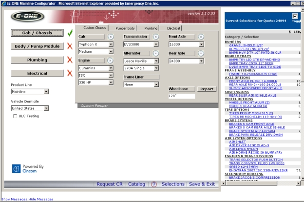
On the Custom Chassis tab, select your Cab first: Cyclone II X, Typhoon X, or Quest. In this example, Cyclone II X is selected to set the rules for the configuration. Either of these cabs may be selected, but one is required.
Next, select your length of cab: Medium or Long.
Cab Options: Selecting Medium, Long, or Extended will affect your wheelbase, compartment widths, Driver and Officer Compartments and pump module.
Select your engine, model, and horsepower.
Select a transmission.
Select an alternator and amperage.
Select a frame liner if needed.
Note: Frame liner is available with a wheelbase of less than 210" (The frame liner is still REQUIRED with a wheelbase of 210" or greater).
Select a front and rear axle.
Note: 21,000lb and 22,800lb Front Axles REQUIRE Front Disc Brakes.
On the Pumper Body tab Displays the Body Door Style, Hosebed Options, Running Board Trays, Body and Pump Module Options, and Ladder and Equipment Options in the Tradition Configurator., select Aluminum or Stainless.
Note: Selecting Stainless Steel from Body will require you to clear out these sections from the Pumper Body tab while clicking the silver 'X' icon.
Front/Rear Compartment Widths
Driver Side
Officer Side
Select Standard, Extended, or Enhanced Extended.
Note: Changing the Body Style will reset the shelves and trays.
Select 3 or 5 compartment for Driver Side.
Select a 3/4 side, Half Side, or Full Side with compartments for Officer Side.
Select Side Mount or Top Mount for Pump Module.
Select a pump module width.
Note: Your body length will determine your pump module width. The default is set to 45" If the pump module is too narrow, then increase the length of the body.
Note: A 4x4 commercial chassis with a 24 inch front compartment requires at least, a 57 inch wide pump module. A 4x4 commercial chassis with a 30 inch front compartment requires at least, a 51 inch wide pump module. A 4x4 commercial chassis with a 36 inch front compartment requires at least, a 45 inch wide pump module.
Select a stack and crosslay.
Select a Water Tank size.
Note: Water Tank Capacity will determine whether the ladder will be through the tank or beside the tank and will determine your Front and Rear Compartment Widths.
On the Plumbing tab Displays the Plumbing Options, Front Plumbing Options, and Right Side Plumbing Options sections in the Tradition Configurator., select a Hale or Waterous Pump.
Select a Model.
Select a GPM.
Note: Pump Rating is constrained by engine horsepower.
Select Akron, Elkhart, or Hale for Valve Brand.
Select a Foam System if needed.
Note: Foam System may be ghosted, but select it anyway if you want it. That will set the system in motion to validate against already selected options. When selecting a CAFS Foam System, a Hot Shift Clutch will be automatically added.
Note: The Foam System selection may now be changed from Dealer Installed to None if a Foam Eductor is selected. When selecting a CAFS Foam System, a Hot Shift Clutch will be automatically added.
On the Electrical tab Displays the Lighting Warning Package, Lower Level Warning Options, Taillight Options, and Electrical Options sections in the Tradition Configurator., select a Forward Light Bar and location.
Select a Lower Warning Light Package a location, and flash.
Select a Side Light Bar if needed.
Click the Cab/Chassis button.
Note: On every tab, and all fields denoted with red rectangles are required selections and must be selected from the drop down lists.
Click the Chassis tab and make your selections. In each drop down list, be sure to scroll down to find the item and select it. Items grayed out are not available.
These buttons are available on the Mainline Configurator window:
Exit: Discards all changes and returns you to the EzONE Hub window.
Request CR: Clicking this button will display the Customer Salescode Request window.
Catalog: Clicking this button will display the Product Catalog.
Help icon: When you click on this button it will display the E-ONE Dealer
Portal WebHelp with the Configurator as the topic in a new window. Scrolling
up and clicking the Show link will
display the WebHelp with the Configurator as the current topic in the
right frame and the topic selected and highlighted in the left frame.
Selections: If this button is clicked after all the selections have been made, a new Current Selections window is displayed inside the Configurator window with a category and a thirty character description link of each selection. Hovering the mouse over the link will display the sales code for that item. Clicking the link will display the Product Catalog for that item. Checking the Toggle Cost box will display the selling price and unchecking it will just display the cost or Dealer Net. The Selections button is available on every tab and can be used to keep a running tally of the price of all the selections made. If this button is clicked before all the selections are made, you will be prompted with dialog boxes to make required selections from each of the tabs that have a red triangle and a red bar for each section to get pricing.
Apply and Exit: Clicking this button before making all the selections will bring up dialog boxes one after the other prompting you to make selections for the other tabs. After these selections are made, you will be returned to the EzONE Hub window. A green check mark will appear next to the button that represents that part of the configuration as valid even though the total configuration is incomplete.
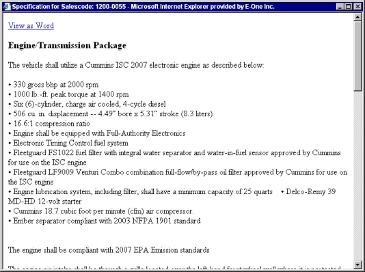
Sales Codes buttons: Clicking on one of these will display the Product Catalog for that item after it has been selected. Clicking the Specification link in the Product Catalog will display the specification in a separate window.

Silver 'X' within a circle icon: Clicking this icon will clear and reset all fields to their default values.
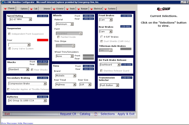
Note: Keep in mind that selecting your Front and Rear Axles earlier will determine your Tire Brand and Rear tread. Reyco Spring Rear Suspension is required and only available with a 31,000lb Rear Axle
Selecting Air from the Rear Suspension section will only allow a 42" or 48" rear compartment.
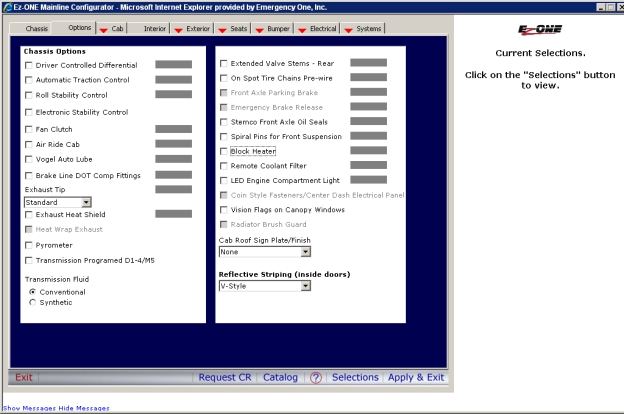
Click the Options tab and make your selections.
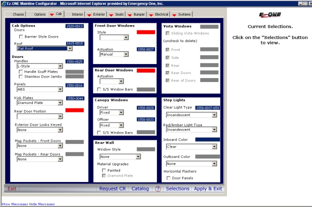
Click the Cab tab and make your selections.
Note: Here are several things to keep in mind when configuring items from each of these sections:
Doors: Selecting Paddle Door Handles will only allow Sliding Actuation for the Rear Door Windows section. Selecting L-Style Door Handles will allow Sliding, Manual, and Power for Actuation in the Rear Windows section.
Vista Windows for Front, Side, Rear, and Rear Doors: Are only available if a 12", 16", or a 20" Vista Roof is selected.
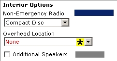
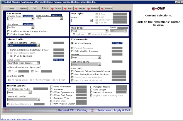
Click the Interior tab and make your selections.
Note: Selecting Cassette or Compact Disc for Non-Emergency Radio under the Electrical section will prompt you with a black and yellow asterisk for a location of this option.
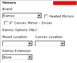
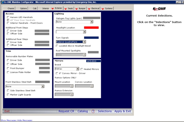
Click the Exterior tab and make your selections.
Note: You will need to select a Headlight Location under the Lighting section.

Note: You will need to select a Mount Location and a Convex Location, if you select Ramco mirrors.
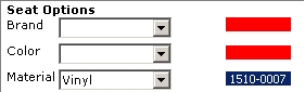
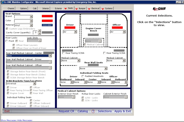
Click the Seats tab and make your selections.
Note: You will need to select a Brand, Color, and Material under the Seat Options section.
Note: You will need to select Driver and Officer Seats for the cab.
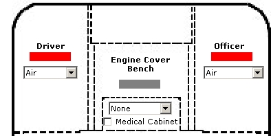
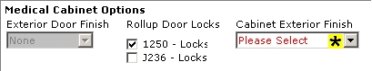
Note: Selecting a Door Finish and Cabinet Exterior Finish for Medical Cabinet Options after selecting Medical Cabinets in the cab will make the Door Brand and Finish the default for the Driver and Officer compartment doors on the truck.
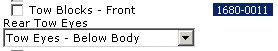
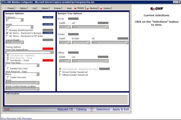
Click the Bumper tab and make your selections.
Note: Selecting Tow Eyes - Below Body from the Rear Tow Eyes section will require a standard departure angle and the Information window Selecting some items in each of the Mainline Configurator .XRA modules will display more information about them at the bottom of the Configurator window. e.g. Selecting Tow Eyes - Below Body from the Rear Tow Eyes section from the Bumper tab of the Cab/Chassis module. confirms this. Otherwise, selecting Tow Eyes - Frame Mounted from the Rear Tow Eyes section will require a 30 degree departure angle. Rear Frame Mounted Tow Eyes are AVAILABLE with Standard Angle of Departure.

Note: Keep in mind that selecting a 20 inch bumper extension under Bumper options will allow you to configure your Driver, Center, and Officer trays. The location of these trays will affect Preconnect/Jump line placement, Primary Siren and Pedestal Mounted Siren placements, and Front Intake placement. Hose Tray Restraints/Lids - This is a REQUIRED selection if Bumper Trays are selected.
Note: Hitch Pre-Wire has been made available in addition to other Hitch selections. If an existing quote is opened, where Pre-Wire is selected, it will need to be re-selected.
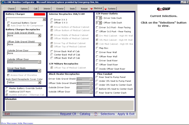
Click the Electrical tab and make your selections.
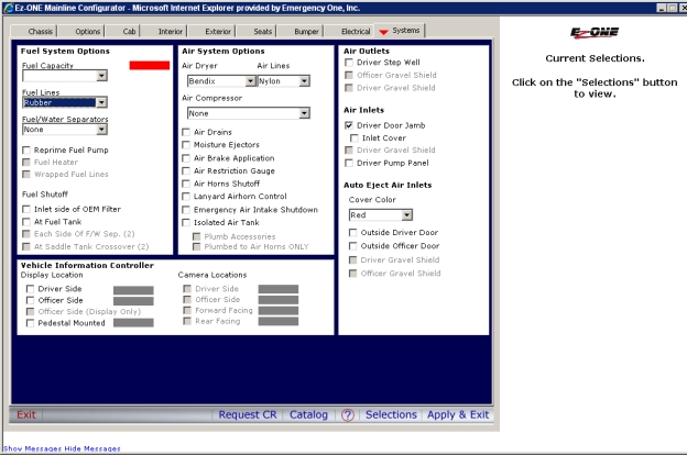
Click the Systems tab and make your selections.
Note: Cover color (red or yellow) is now a required selection for auto eject air inlets.
Click the Selections button to display the price list.
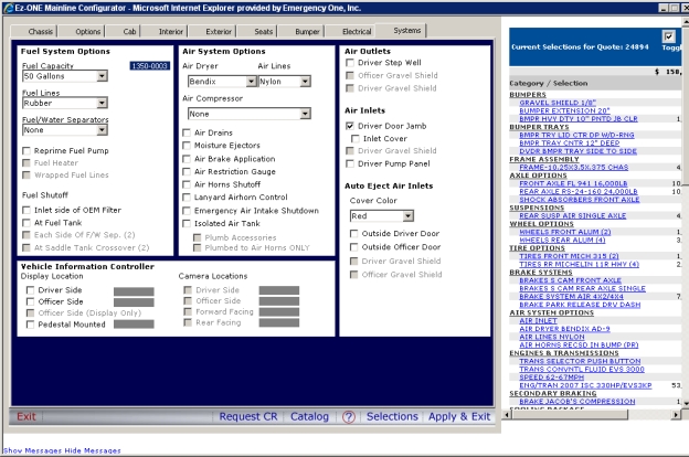
Click the Apply and Exit button, the configuration is validated and a green checkmark appears next to the Cab/Chassis button on the following page.
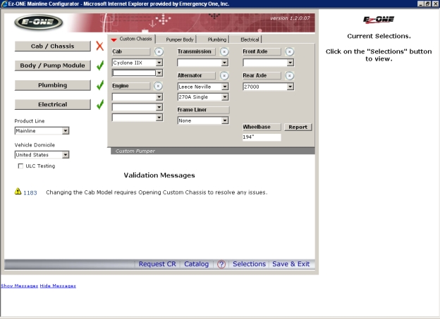
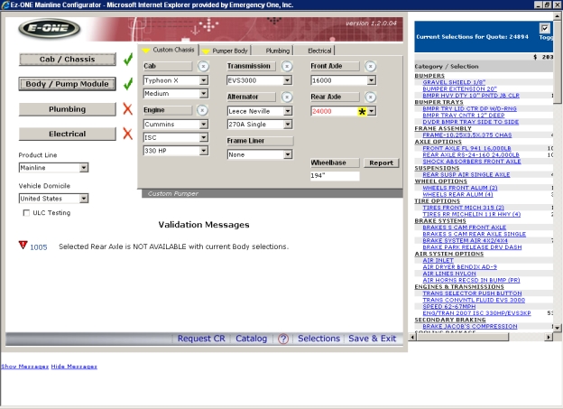
Switching from a Cyclone II X chassis to a Typhoon X chassis and clearing out the engine, transmission and front axle with the silver X will cause a red X to appear next to the Cab/Chassis button and yellow arrows to appear on the various tabs inside the Cab/Chassis module. A validation message will also appear requiring you to open the custom chassis to resolve the issues. Once re-selections are made the price drops. To re-price, make the necessary changes for each of the yellow tabs and click the Selections button. Use the scroll bar to scroll the Selections window to the left. Use the arrow keys on your keyboard to scroll up, down, left or right. If you have a wheel mouse, use the wheel to scroll up or down.
Re-select the cab length, engine, transmission, and front axle from the Custom Chassis tab.
Click the Cab/Chassis button. Any yellow arrows on the tabs mean that items are invalid and will need to be fixed to resolve the issue with the configuration. In this case, there are none.
When the Apply and Exit button is clicked the configuration is validated and a green checkmark appears next to the Cab/Chassis button on the following page. Red Xs next to the Body/Pump Module Clicking this button in the Mainline Configurator will load the Body/Pump Module .XRA module and allow you to configure items for that module., Plumbing, and Electrical buttons mean that these sections have not been configured yet. The Current Selections window is populated with the categories, selections, and prices of the items.
Click the Body/Pump Module button.
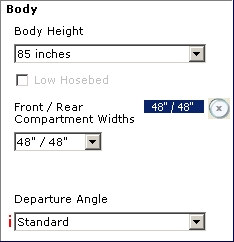
On the Body tab, make your selections.
Note: Selecting Tow Eyes - Below Body from the Rear Tow Eyes from the Rear Tow Eyes section was selected from the Bumper tab of the Cab/Chassis module and requires a standard departure angle. In this example, Standard needs to be selected from Departure Angle in the Body section. The red 'i' icon means that an invalid selection can be made for that object. i.e.: you can pick it even if it's greyed out.
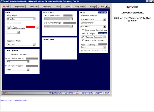
Note: Electric Newton Dump with a Full Height Rear REQUIRES a Deep Upper Compartment
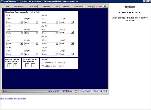
Click the Requirements tab and make your selections.
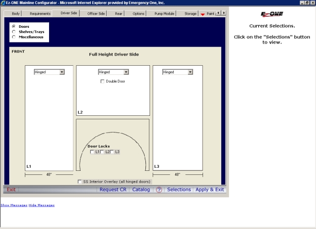
Click the Driver Side tab and make your selections for Doors.
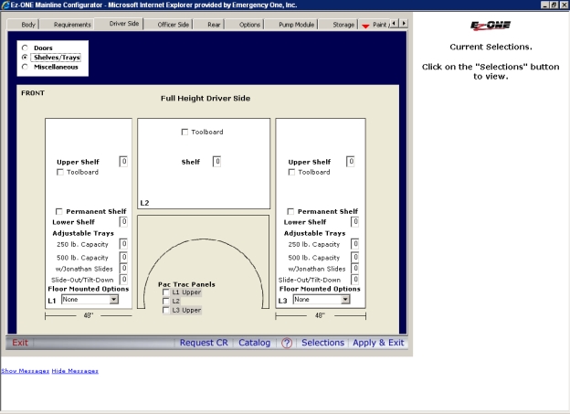
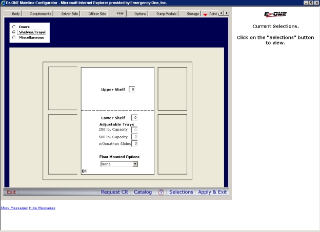
Click the Shelves/Trays radio button and make your selections.
Note: Shelves and trays are limited to 5 per location.
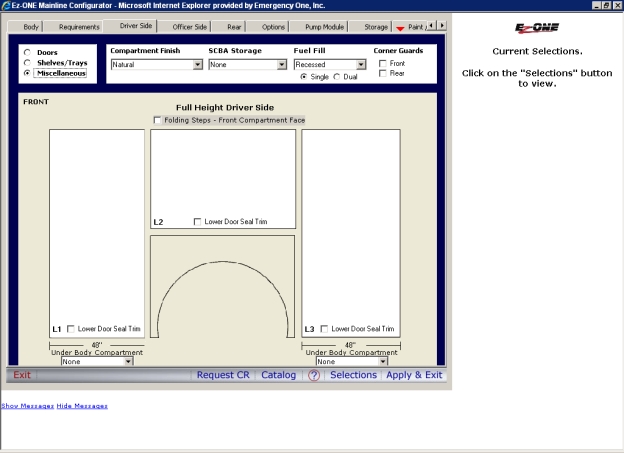
Click the Miscellaneous radio button and make your selections.
Note: Under Compartment Finish, selecting Zolatone Gray means that only the compartment walls will be painted. Selecting Zolatone Deluxe Gray means that the compartment walls, shelves and trays will be painted.
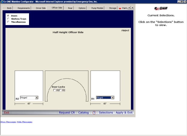
Click the Officer Side tab and make your selections for Doors.
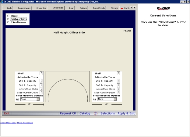
Click the Shelves/Trays radio button and make your selections.
Note: Shelves and trays are limited to 5 per location.
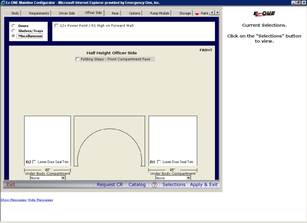
Click the Miscellaneous radio button and make your selections.
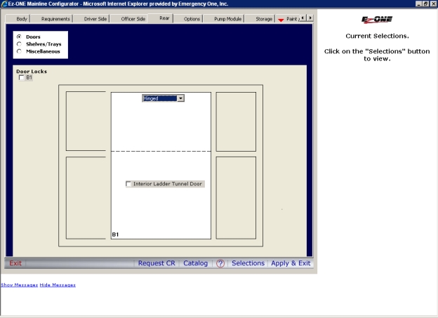
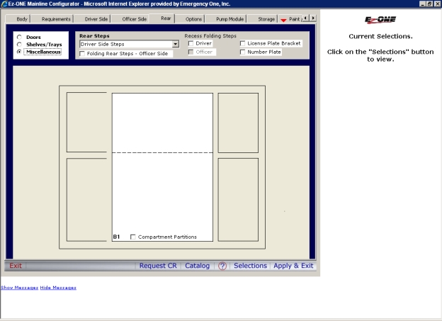
Click the Rear tab and make your selections for Doors.
Click the Shelves/Trays radio button and make your selections.
Note: Shelves and trays are limited to 5 per location.
Click the Miscellaneous radio button and make your selections.
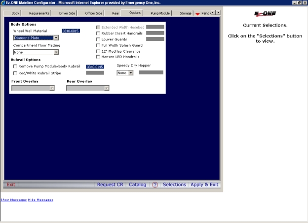
Click the Options button and make your selections.
Click the Pump Module tab and make your selections.
Note: Transverse Module Compartment Doors (Painted, Diamond Plate, Satin and Painted Rollup) are REQUIRED selections if a Transverse Module is selected. Driver and Officer Doors may be selected independently.
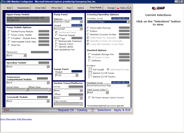
Note: Please be sure to enter something in the Enter Tag Label Color Text: field as a placeholder for Panel Tags.
Note: Not checking the Painted Pump Module box from the Pump Module Options section will result in a $1000 savings.

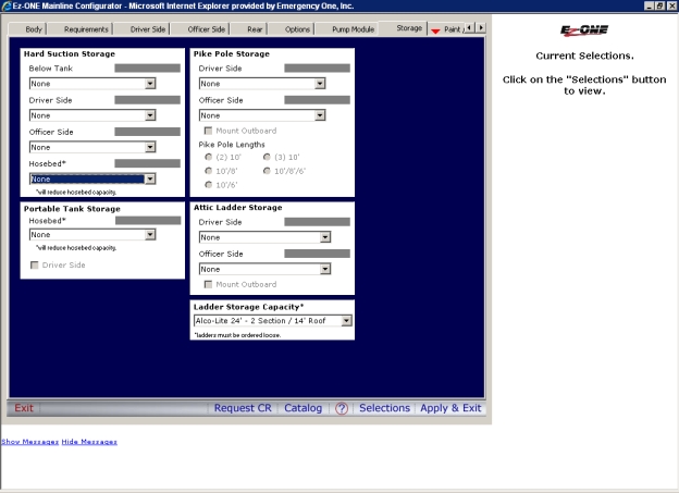
Click the Storage tab and make your selections.
Note: Portable Tank Storage Box located in the officer side hosebed (Requires a front compartment width of 36" or greater)
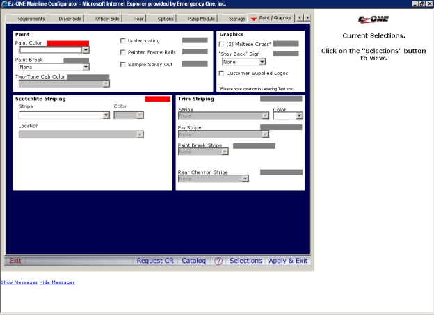
Click the Paint/Graphics tab and make your selections.
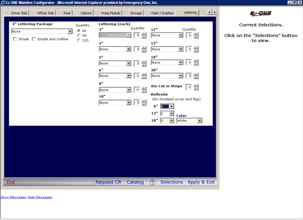
Click the Lettering tab and make your selections.
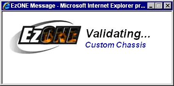
Click the Apply and Exit button. The Ez-ONE Message dialog box appears validating your configuration.

A green checkmark appears next to the Body/Pump Module button on the following page. Red Xs next to the Plumbing, and Electrical buttons mean that these sections have not been configured yet. Yellow arrows on the Custom Chassis and Pumper Body tabs mean that some selections will need to be fixed.
Click the Plumbing button Clicking this button in the Mainline Configurator will load the Plumbing .XRA module and allow you to configure items for that module..
Note: If you are having problems trying to advance to the next tab (e.g. Preconnects to Intakes), you will need to re-click the tab you are on again and then you will be able to click on tab you want to go to. This is a bug in the Cincom software where a tab may lose its focus. The focus is the rectangle around the tab name.
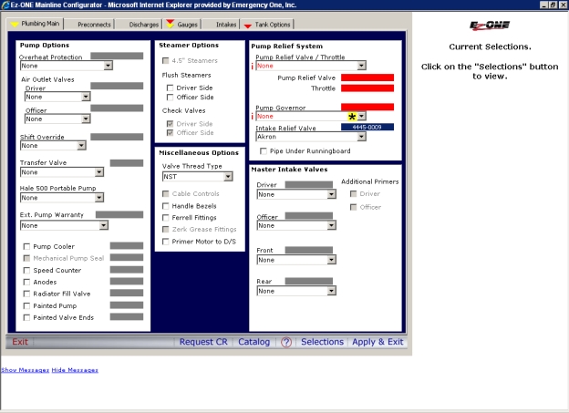
On the Plumbing Main tab make your selections.
Note: Selection of Cable Controls will require at least a 45 inch wide Pump Module.
Note: Leaving the Mechanical Pump Seal box unchecked will only have pump packing as a standard option. Checking the box will allow you to upgrade to a Mechanical Pump Seal.

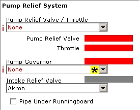
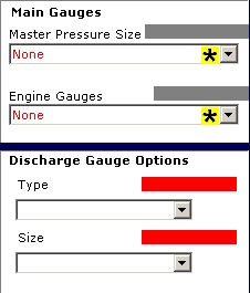
Note: You will need to select a Pump Relief Valve/Throttle and/or a Pump Governor. The type of Pump Relief Valve/Throttle you select will determine if a Pump Governor is required. The type of Pump Governor you select will determine if Master Pressure and Engine Gauges are required under the Main Gauges section on the Gauges tab. If you want the Master Intake Valve on both the Driver and Officer sides then you must pick the Master Intake Valve first before selecting a Pump Relief Valve / Throttle. Otherwise, just pick the Pump Relief Valve / Throttle and then the Master Intake Valve.
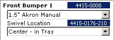
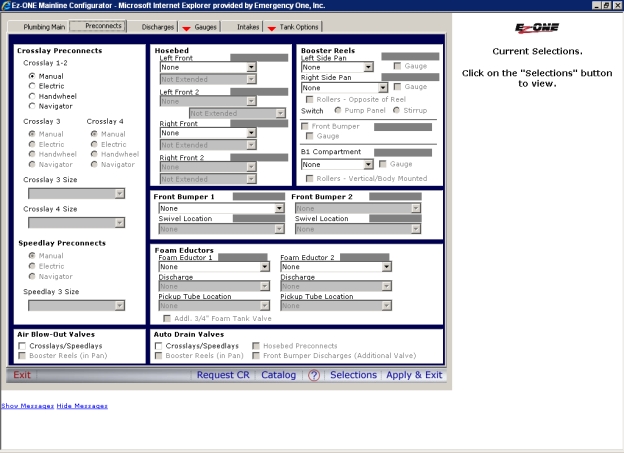
Click the Preconnects tab and make your selections.
Note: Placement of a Preconnect on the Front Bumper is restricted by Front Intake and Pedestal Mounted Sirens locations. In the earlier example, a 24 inch bumper extension with a center tray was select earlier. In this example, selecting a 1.5 inch Akron Manual and Center in Tray Swivel Location will allow a Driver Side Pedestal Mounted Siren and an Officer 5 inch Front Intake with a Swivel or Adapter on the Front Bumper. These are the interdependencies to keep in mind as you configure your truck.
Note: Foam Eductors can be selected whether or not a foam system is installed on a truck.
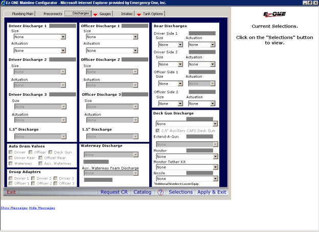
Click the Discharges tab and make your selections.
Note: When an Auto Drain Valve is NOT selected for a discharge, Bleeder Valves will be added automatically.
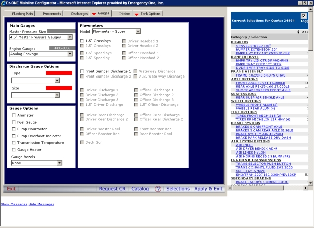
Click the Gauges tab and make your selections.
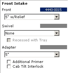
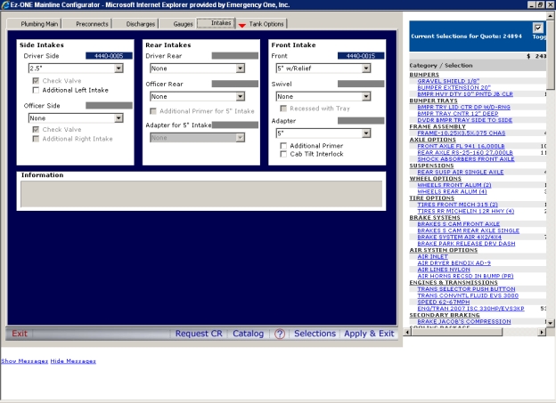
Click the Intakes tab and make your selections.
Note: Since the 20 inch bumper extension under Bumper options was selected and Center Tray was selected earlier, a Front Intake can now be selected for the Officer Side along with an adapter or a swivel. In this example, a 5 inch Front Intake with Relief through the bumper and a 5 inch Adapter is selected.
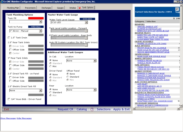
Click the Tank Options tab and make your selections.
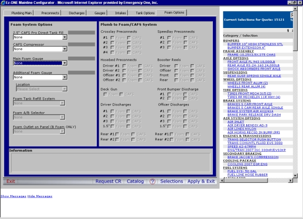
Click the Foam Options tab and make your selections.
Note: This tab only appears if a foam tank and a foam system is selected.
Note: An information window has been added to assist in determining the maximum number of discharges that may be plumbed to a foam system.
Driver and Officer Discharges Plumbed to Foam (one each side)
Changes are being made to allow the selection of a discharge to be Plumbed to Foam or Plumbed to CAFS (if a CAFS system is selected).
If a quote is opened that has a CAFS system selected, the Plumb to CAFS selection will need to be made for the following discharges: Crosslays, Speedlays, Hosebed Preconnects, and Booster Reels.
If Plumb to CAFS is NOT SELECTED, the discharge will be considered Plumbed to Foam ONLY.
The discharges not listed above have been upgraded in the 1.0.0.71 release of Ez-ONE Mainline.
Ez-ONE Mainline also allows the selection of a discharge to be Plumbed to Foam or Plumbed to CAFS (if a CAFS system is selected).
If a quote is opened that has a CAFS system selected, the Plumb to CAFS selection will need to be made for ALL discharges.
Once again, If Plumb to CAFS is NOT SELECTED, the discharge will be considered Plumbed to Foam ONLY.
Click the Apply and Exit button. The Ez-ONE Message dialog box appears validating your configuration.
A green checkmark appears next to the Plumbing button on the following page. A red X next to the Electrical button Clicking this button in the Mainline Configurator will load the Electrical .XRA module and allow you to configure items for that module. means that this section has not been configured yet.
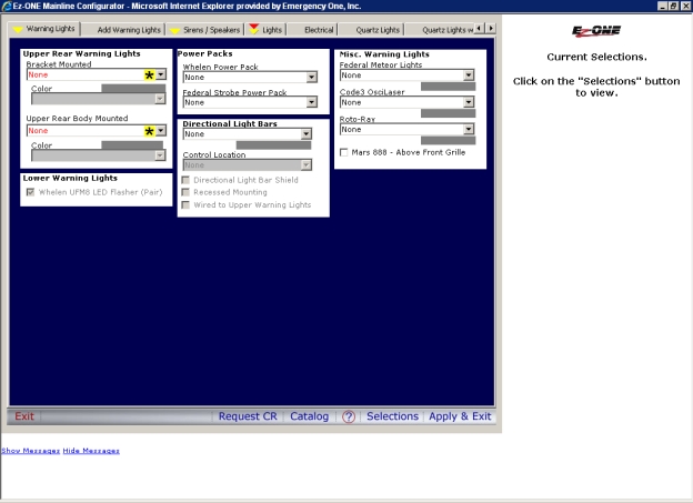
Click the Electrical button.
Note: If you are having problems trying to advance to the next tab (e.g. Warning Lights to Sirens / Speakers), you will need to re-click the tab you are on again and then you will be able to click on tab you want to go to. This is a bug in the Cincom software where a tab may lose its focus. The focus is the rectangle around the tab name.
Click the Warning Lights tab and make your selections.
Note: The brand of Lightbar for the Forward Lightbar must match the brand of Bracket Mounted Upper Rear Warning Lights.
Note: Federal Signal Vector/ViewPoint LED light bar (5300-0097) on a cab with vista roof, requires the removal of the front vista windows.
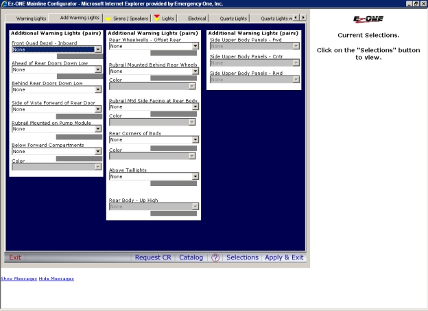
Click the Add Warning Lights tab and make your selections.
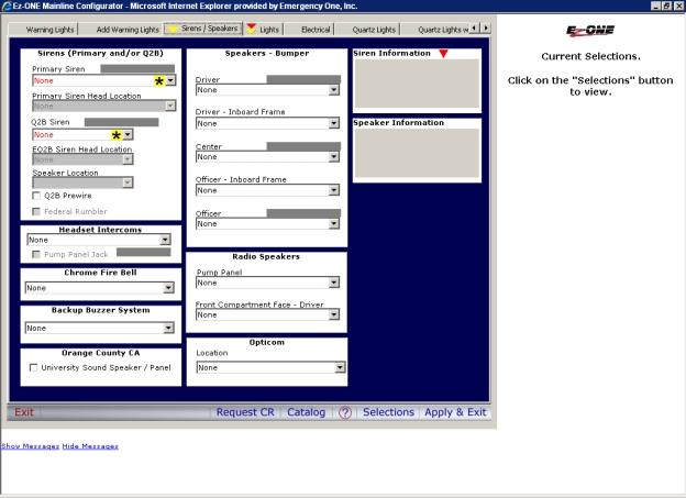
Click the Sirens/Speakers tab and make your selections.
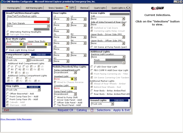
Click the Lights tab and make your selections.
Note: Compartment Lights selections are as follows:
|
Brand |
Type |
|
POK |
LED |
|
ROM |
LED or Halogen |
|
Truck-Lite |
LED or Incandescent |
Note: Door Lights and Step Lights will either be LED or Incandescent.
Click the Electrical tab and make your selections.
Note: A few things to keep in mind while configuring options on the Electrical tab.
When a Generator is selected from the Generator section, an 8 panel breaker is automatically added. An additional 2 circuit panel may be selected if desired.
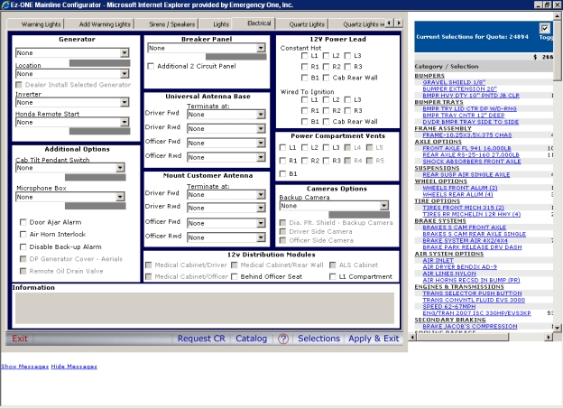
Note: All quotes with Antennas selected MUST RESELECT these options, due to product offering changes.
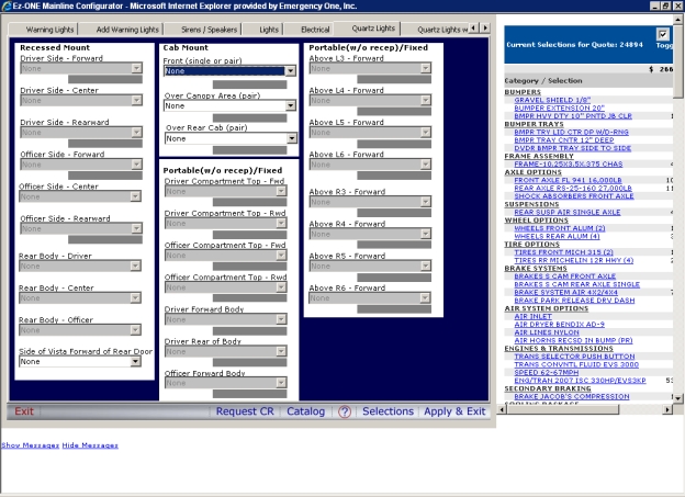
Click the Quartz Lights tab and make your selections.
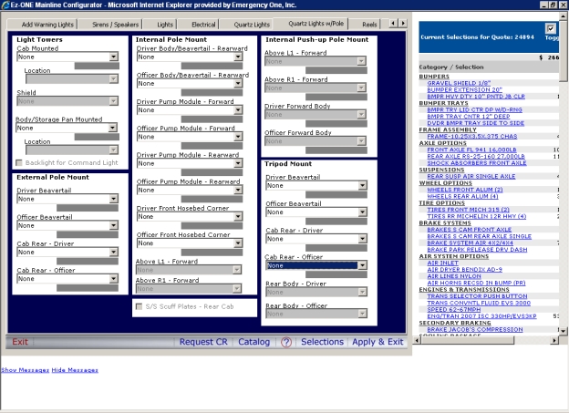
Click the Quartz Lights w/ Pole tab and make your selections.
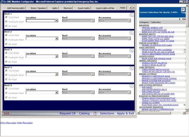
Click the Reels tab and make your selections.
Note: This tab will encompass all reels (Cord, Hydraulic, and Air). There are selections for five reels no matter the type. The default is Cord reels just as it was with the multiple selections before. Select the Location first. If the reel type is not grayed out, you may switch to a Hydraulic or Air Reel (depending on the location). The Reel drop down will then be available for selection as well as the Accessory (Junction Boxes, Cord Connectors, Hydraulic Lines).
ALL Quotes containing reels must reopen Electrical then Save and Exit for their existing reels selections to populate the new Reels tab.
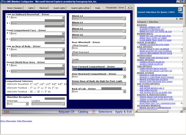
Click the Receptacles - Driver tab and make your selections.
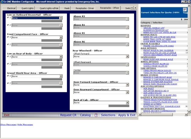
Click the Receptacles - Officer tab and make your selections.
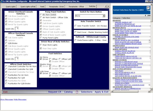
Click the Switches tab and make your selections.
Click the Apply and Exit button. The Ez-ONE Message dialog box appears validating your configuration. Next, the Generating... Salescodes message box appears.

A green checkmark appears next to the Electrical button on the following page.
Click the Save/Exit button and the Generating.... Salescodes message box appears. The Quote window is displayed with the Quote Number with revision number and Unit Information. At this point, you can enter the Customer Information, Dealer Reference, and Date Information. For Quote Actions, you can click these links: Copy Quote, Delete Quote, Workflow Workflow Workflow is the electronic method used to send a quote for a bid bond request, concession request and/or as an order to the appropriate group. This will speed up the turnaround time for requests on quotes. is the method used to send a quote for a concession request and/or as an order to the appropriate group. This will speed up the turnaround time for requests on quotes. Quote, Print Page, Request CR, and Save Quote button.
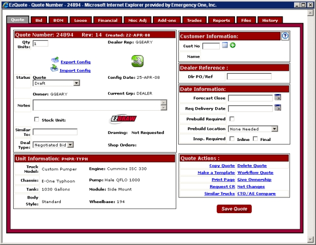
After a truck has been configured in the Configurator, the Quote tab will display the Quote Number, Revision Number, Date Created, Unit Information, Customer Information, Dealer Reference, Date Information, and Quote Actions. Note that the red icon with the wrench has turned green meaning a truck has been configured in the Configurator.

At this point go to the BOM tab topic to learn more about the EZQuote window.
Related Topics:
Working With an Existing Quote